Dense Multi-Port Optical Component Solutions
Using Impact Mount Technology (IMT)
Michel Rondeau, Shin-Lo Chia
Valdor Fiber Optics Inc., 2621 Barrington Court, Hayward, CA 94545 Tel: (510) 293-1212, Fax: (510) 293-9777 email: miche@valdor.com
Davis H. Hartman
11451 East Desert Troon Lane, Scottsdale, AZ 85255 Tel: (480) 513-2585, Fax: (480) 513-0608, email: dhhii@ieee.org
Abstract: Impact mount technology (IMT) is a method of manufacturing low cost fiber
assemblies. We describe a progeny of IMT, called HeptoPort, which represents a major
manufacturing breakthrough for scalable low cost self-aligned, multi-port optical component
design. Assembly technique and physical architecture are described.
©2000 Optical Society of America
OCIS codes: (060.2340) Fiber Optics Components, (220.1140) Alignment
1. Introduction – System Context
Currently, in the telecom industry, technology is far ahead of the marketplace. Of the three design drivers, cost, performance, and reliability, cost heavily dominates the list. Market dynamics are pressuring manufacturers to produce fiber optic components at very low cost; but they cannot support the economy of scale that traditionally accompanies high volume manufacturing.
There is, however, still demand for performance and reliability at the right price. Important performance issues such as wavelength and port scalability, loss uniformity, and modularity can only be achieved through manufacturing innovation, whereby tight process control parameters produce the desired results. The emerging importance of manufacturing innovation to component and module performance represents a paradigm shift for the optical communications industry [1]. Impact Mount Technology (IMT), and its progeny, HeptoPort™, typifies this paradigm shift. Multiple ADMs, DWDM selectors, isolators, interleavers, and many other functions can be incorporated in a single component, sharing the cost of expensive elements such as filters, lenses, etc.
2. Impact Mount Technology (IMT)
(b)
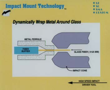
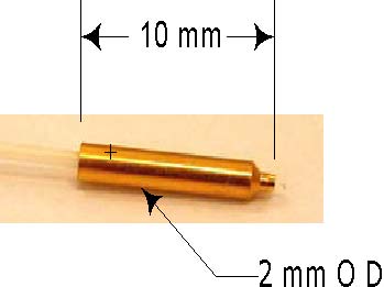
Figure 1 - (a) Schematic depiction of the IMT process. The metal ferrule is compression fit directly onto the glass surface of the optical fiber. (b) Photograph of a Kovar ferrule impact mounted with an on 8° APC bare fiber.
IMT is a radial compression fit of a ductile metal around a cylindrical glass surface. The need to metallize optical fiber is obviated by Impact Mount Technology (IMT). Figure 1 illustrates a single fiber ferrule IMT process. Attachment of metal ferrules to the fiber(s) occurs in one fast mechanical action. This action, called the impact, occurs between the stripped fiber and ferrule, using a precision impact mount die. The Impact Mount connectors/ferrules are made from various metal alloys, the most common types being stainless steel and copper-nickel alloy. The main body of the connector can be all metal or constructed with glass-reinforced polymer.
For a single fiber operation, the result is a hermetic mechanical fit of the fiber to the inside of the ferrule. The process satisfies Telcordia GR-488 environmental exposure requirements. Fibers with IMT ferrules maintain helium leak rates of 2.7x10⁻¹¹ atm.-cc/s over 2000 thermal cycles of -40oC to 100oC. Pull-test results on the fiber pigtails exceeded the 1kg requirement and the fiber piston movement was typically less than 80nm. The ferrule is attached to the package via laser welding or solder processing.
The IMT process is well suited for machine automation. It is used in production of fiber pigtails for telecommunications applications [2]. The fiber pigtail preparation may also be readily integrated with automated alignment and attachment stations when using IMT to attach the ferrule onto the fibers.
3. HeptoPort Technology
Experience with IMT has led to a new concept for affixing and terminating multiple fibers, with extraordinary self-alignment features. The mechanical compression in IMT is so uniform that it can be used to affix fiber bundles in hexagonal close-packed arrangements within a ferrule. The circular symmetry inherent to hexagonal close-packed fiber bundles lends itself naturally to the IMT method. IMT guides, in one instantaneous action, arrays of stripped optical fibers to their natural hexagonal close-packed arrangement, like marbles falling into a box. The alignment of the positions of the centers of the surrounding “planetary” fibers, relative to the center “sun” fiber, is determined entirely by the uncertainties in fiber outside diameter, circularity, and core/cladding concentricity. These uncertainties are less than 0.6 microns, worst case, for the seven-fiber HeptoPort™ configuration.
Figure 2 shows a scanning tunneling electron microscope photograph of the end face of an IMT ferrule mounted with seven ports. The ductile metal has surrounded the fiber bundle, and all seven fibers are in contact with each other. They have found their naturally preferred positions in the hexagonal close-packed configuration.
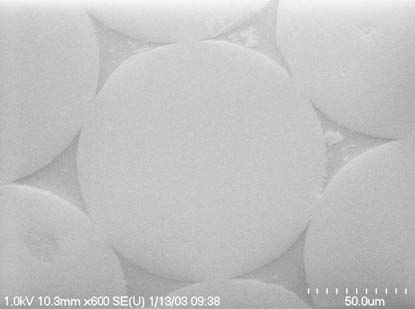
Figure 2 - STEM photograph of a HeptoPort structure, showing self-alignment of the seven fibers.
Beam BeamExpansion/Collimation Contraction/Re-focusing
Seven Fiber IMT
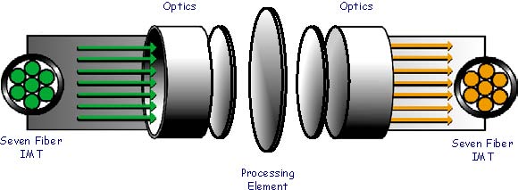
Figure 3 – Diagram of the HeptoPort™ architecture, including seven-fiber IMT multi-port I/O, expanded beam optics, and processing element. Different processing elements can be incorporated into this architecture, resulting in different functions, without requiring retooling.
The HeptoPort concept is embodied in a physical architecture, shown in Figure 3. This architecture suggests a new genre of multi-port applications in the optical communications industry. The technology and its associated architecture are called HeptoPort. Utilizing IMT and expanded beam optics as an integral part of the physical structure, it is possible to produce a variety of external functionalities by implementing different processing elements in the HeptoPort body. Two examples of this concept are WDM add-drop multiplexers and isolators.
4. Applications
A typical bill of materials for an opto product consists of 60 to 70% opto/package-related items (Figure 4). Most of this cost is consumed in solving the difficult optical alignment issues, and then qualifying the products using the chosen solution. HeptoPort™ gives the designer a means to reduce alignment and packaging costs directly. Additionally, these costs can be amortized over a number of independent units. This is accomplished by sharing multiple ports over a single ferrule, which is as easy to align as a single unit. An added benefit to this approach comes with the compact design of the ferrules. Fiber pitch using HeptoPort™ alignment is 125 microns; twice as small as the MT array configuration offers. For example, using HeptoPort™ multi-port solutions, arrays of hexagonal close-packed arrays of single mode fibers could be aligned to VCSEL arrays patterned in the same array configuration. The result would be seven, 10, or even 37 fiber/VCSEL devices aligned using methods not too different than those employed for single fibers.
Using HeptoPort technology, arrays of like-functions can be integrated onto the same physical structure. Implementing the HeptoPort architecture for integrating multiple components dramatically reduces cost. For a 2x1 add/drop multiplexer the number of thin film filters and GRIN lenses is halved. Thus, there is reduction in module component bill-of-materials (BOM) cost of 50%. The reduced degrees of freedom and component alignment variances also allows for lower assembly costs. The multiplexer footprint area is halved. This configuration also improves channel isolation by -10dB, and allows for bi-directional multiplexer operation.
Two examples of the concept are ADMs and isolators. In each case, the critical processing element (filter, in the case of ADMs, and quarter wave plate, for isolators) is shared among a number of functionally Figure 4 independent, but coexisting units. Since an ADM is a three-port device, two units can be implemented in a single 2-mm HeptoPort ferrule. For isolators, which are two port devices, up to seven can be shared, with directionality being an application-dependent design parameter. Clearly, many other passive optical functions using HeptoPort can be imagined. Because multiple fiber arrays are self-aligned, and because circular symmetry is preserved, alignment of arrays of fibers to active electro-optics, such as VCSEL arrays, is greatly alleviated.
Table 1 shows histogram data on port reflection and throughput loss, for a representative sample of ten three-fold OADM units, integrated onto the HeptoPort seven-fiber structure. As shown, both reflect-port and pass-port loss are not only low, but consistent across the tri-fold units in each HeptoPort structure, and from one tri-fold unit to the next.
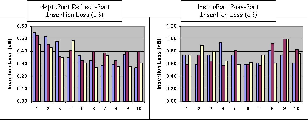
Table 1
5. Summary
IMT and HeptoPort represent a paradigm shift in optoelectronic packaging. Offering unparalleled self-alignment features with significant cost reduction for the module designer, HeptoPort opens an entirely new set of physical design options for the optical networking industry.
[1] Carlisle, Brian, “Precision Assembly Automation”, Proceedings, NEPCON West / Fiber Optic Automation Expo, McEnery Convention Center, San Jose, CA, December 3 - 6, 2002.
[2] http://www.valdor.com/products00/np1.html